LINK:
http://www.we-r-here.com/cad/tutorials/level_3/3-11.htmFirst, to explain the funny name : "It was named after George Boole, who first defined an algebraic system of logic in the mid 19th century."
Working in 3D usually involves the use of solid objects. At times you may need to combine multiple parts into one, or remove sections from a solid. AutoCAD has some commands that make this easy for you. These are the boolean operations as well as some other helpful commands for solids editing.:
|
COMMAND
|
INPUT
|
ICON
|
DESCRIPTION
|
|
UNION
(Boolean)
|
UNI |

|
Joins two or more solids into creating one based on the total geometry of all.
|
|
SUBTRACT
(Boolean)
|
SU |

|
Subtracts one or more solids from another creating a solid based on the remaining geometry.
|
|
INTERSECT
(Boolean)
|
IN |

|
Creates a single solid from one more solids based on the intersected geometry.
|
|
EXTRUDE FACE
|
SOLID EDIT |

|
Allows you to increase the size of a solid by extruding out one of its faces.
|
|
SLICE
|
SLICE |
 |
Slices a solid along a cutting plane.
|
|
3D ALIGN
|
3DALIGN |
 |
Aligns 2 3D Objects in 3D space.
|
The boolean commands work only on solids or regions. They are easy to work with IF you follow the command line prompts. Here is an example of each.
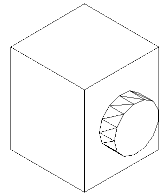
Start these exercises by drawing a box 5W X 7L X 3H and a cylinder 3 units in diameter so that the center of the circle is on the midpoint of the block.
UNION
Below left, there is a box and a cylinder. These are two separate objects. If you want to combine them into one object, you have to use the union command.
 |
 |
|
The UNION command combines one or more solid objects into one object.
|
Here are the command line prompts and the resulting object:
Command: UNION <ENTER>
Select objects: <SELECT THE BLOCK> 1 found
Select objects: <SELECT THE CYLINDER> 1 found
Select objects: <ENTER>
NOTE: The object that you select first will determine the properties of the unioned object when it is created.
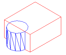
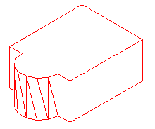
SUBTRACT
The subtract command is used to cut away, or remove the volume of one object from another. It is important to check the command line when using this command. Remember that AutoCAD always asks for the object that you are subtracting FROM first, then it asks for the objects to subtract. Here is an example:
|
 |
|
The SUBTRACT command removes the volume of one or more solid objects from an object.
|
Command: SUBTRACT
Select solids and regions to subtract from...
Select objects: <SELECT THE BLOCK> 1 found <ENTER>
Select objects: Select solids and regions to subtract...
Select objects: <SELECT THE CYLINDER> 1 found <ENTER>
Select objects: <ENTER>
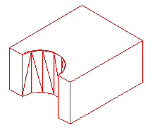
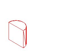
INTERSECT
This command creates a new solid from the intersecting volume of two or more solids or regions. AutoCAD will find where the two objects have an volume of interference and retain that area and discard the rest. Here is an example of this command shown below:
|
 |
|
The INTERSECT command combines the volume of one or more solid objects at the areas of interference to create one solid object.
|
Command: INTERSECT
Select objects: <SELECT THE BLOCK> 1 found
Select objects: <SELECT THE CYLINDER> 1 found
Select objects: <ENTER>
Try these commands with various 3D solid objects to get familiar with them. Draw the block in Lesson 3-2. Draw the outline of the block, extrude it - then draw the circle and extrude it. Then subtract the circle from the block.
These commands will allow you do a lot of 3D work, using only the extrude and these boolean commands. Of course, there are some other ways to edit 3D solids.
SLICE
This command does exactly what the name implies. You can slice a 3D solid just like you were using a knife.
Start with the basic block and cylinder shape you used in the examples above.
 |
 |
|
The INTERSECT command combines the volume of one or more solid objects at the areas of interference to create one solid object.
|
Command: SLICE
Select objects: 1 found
Select objects: Specify first point on slicing plane by
[Object/Zaxis/View/XY/YZ/ZX/3points] <3points>: PICK POINT 1
Specify second point on plane: PICK POINT 2
Specify third point on plane: PICK POINT 3
Specify a point on desired side of the plane or [keep Both sides]: <Pick on the side towards the cylinder>
This is a very useful command - think of it as a trim in 3D. Make sure you have your Osnaps on for this command and that you pick the correct points. In a complex 3D drawing, this can be tough to see.
EXTRUDE FACE
Just as there is a "trim"-like command in 3D - there is also a "stretch". This is a new command in recent versions. 
I usually start this command by clicking on the menu item Modify > Solids Editing > Extrude Faces. There is also an icon for it on the Solids Editing menu.
The command is quite easy to use, but you need to be careful on which face you select.
Try to extend one edge of the block by 1 inch. Start the command and pick the face on the side (on the bottom line). You'll notice that the bottom face highlights as well. Next type R and pick the bottom face to remove it. Then follow the command line to finish the command.
Command: _solidedit
Solids editing automatic checking: SOLIDCHECK=1
Enter a solids editing option [Face/Edge/Body/Undo/eXit] <eXit>: _face
Enter a face editing option
[Extrude/Move/Rotate/Offset/Taper/Delete/Copy/coLor/Undo/eXit] <eXit>: _extrude
Select faces or [Undo/Remove]: (PICK BOTTOM LINE OF SIDE FACE) 2 faces found.
Select faces or [Undo/Remove/ALL]: R
Remove faces or [Undo/Add/ALL]: (PICK AN EDGE ON THE BOTTOM FACE)2 faces found, 1 removed.
Remove faces or [Undo/Add/ALL]: (ENTER)
Specify height of extrusion or [Path]: 1 (ENTER)
Specify angle of taper for extrusion <0>: (ENTER)
Solid validation started.
Solid validation completed.
Enter a face editing option
[Extrude/Move/Rotate/Offset/Taper/Delete/Copy/coLor/Undo/eXit] <eXit>: (ENTER)
You should end up with this:
Another way of editing faces in AutoCAD 2007 is to use grips to extrude the faces, just like you would on a 2D object. Here is an image below that shows some of the grips available.This option is only available on the basic shapes shown in lesson 3-10.

3D ALIGN
Sometimes, you may find it faster or easier to draw something separately and then move and align it into place. The command to use this in 3D is (funnily enough) 3DALIGN.
This is a simple example, but will show you the method.
Draw a box that is 5 x 5 x 6 tall. Next draw a cylinder that is 3 in diameter and 1 tall. It should look like this:

The goal will be to align the cylinder on the front face of the box where the dotted line is.
Turn on your quadrant Osnaps. Start the 3DALIGN command. You will first be asked to select the objects - select the cylinder and press enter.
Now you will be asked to select the 3 points as indicated below: the centre and 2 quadrants. Now the cylinder will be "stuck" to your cursor as AutoCAD asks where it needs to go.
Line the cylinder up with the box by using object tracking to locate the centre of the face on the box first. Then pick on the midpoints to line up the cylinder to the box. After you pick the 3rd point, the cylinder should move into place and end the command.
Here's a view of the points that were picked incase you had trouble.

The finished 'alignment job' should look like this after using the hide command.
Review:
After learning how to draw some basic 3D solids, you can see that using equally basic editing commands you can have a lot of options. Before advancing, review these commands by drawing simple 3D shapes and editing them.
With the commands explained on these pages, you will be able draw most of the shapes you will need in 3D. There are other options, but get very familiar with these 3D editing options before moving on. The drawings done in the sample drawing section were done almost exclusively with the commands taught in Lessons 3-7 to 3-11. You approach will make the project easy or difficult. Think of the various ways to draw an object before starting. You could save days with some forethought.
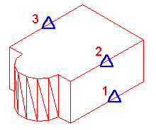
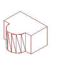
Extra Practice: Draw this object as a 3D solid using primitive solids and boolean operations.
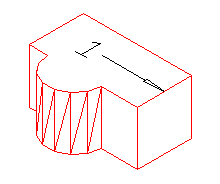
Extra Practice: Draw this object as a 3D solid using primitive solids and boolean operations.